In the ever-evolving landscape of CAD design, precision and ease of use is paramount. BobCAD-CAM has a suite of features, designed to elevate your design experience and streamline your workflow. Let’s delve into a few of the capabilities that BobCAD-CAM brings to the table:
1. Construction Geometry Function: A Versatile Assistant
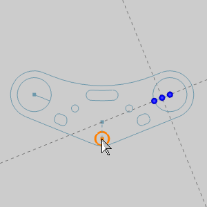
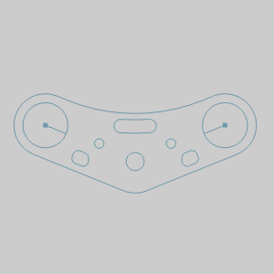
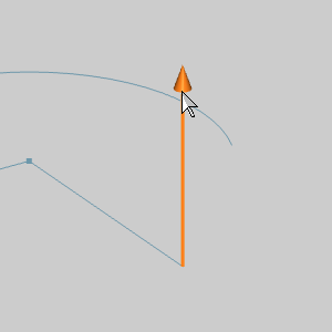
Construction Geometry is a dynamic function easily toggled by clicking the ![]() icon at the bottom of the user interface. When activated, this function becomes your versatile assistant, offering a range of aids to enhance your design process:
icon at the bottom of the user interface. When activated, this function becomes your versatile assistant, offering a range of aids to enhance your design process:
- Horizontal and Vertical Indicators
- Intersection Indicators
- Tangency Indicators
- Perpendicular to Arc End
- Tangent to Arc End
- Arc Center
- Vertical to Arc Center
- Horizontal to Arc Center
Effortlessly turn these indicators on or off, depending on your specific design needs.
| Using Construction Geometry | Placement |
 |
 |
.
2. Modify Entities: Elevating Editing Efficiencies
When the need arises to modify an entity, the process is now smoother than ever. Enter selection mode and double-click on the entity in question. The modify dialog opens seamlessly, allowing you to adjust various parameters and sketch handles for the following entities:
- Points
- Lines
- Full and Partial Arcs
- Texts
This streamlined modification process enhances precision and saves valuable time.
| Double-click Entity | Select Modification Option | Quickly Extend |
 |
 |
 |
.
3. Select Layer(s) Dialog: Simplifying Layer Management
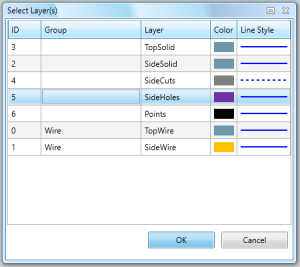
The Select Layer(s) dialog, provides comprehensive layer information, sorting options, and the ability to select multiple layers simultaneously. This enhancement ensures a more organized and efficient layer management experience.
| Select Layer(s) Dialog |
 |
.
4. Selection Manager: Efficient Grouping of Entities
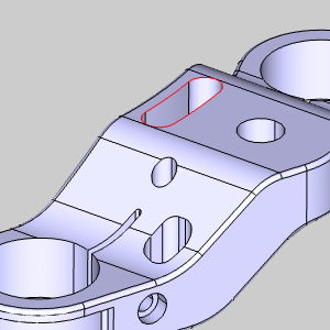
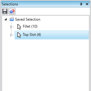
The Selection Manager empowers you to select any number of entities and save them as a single selectable item. This innovative feature allows you to group entities efficiently, enabling you to select them collectively with a single click in future operations. This is a fantastic way to pre-select geometry for your CAM features while creating your CAD!
| Select Entities for CAD Function | Save for Automatic Selection | Instantly Select All Entities |
 |
 |
 |
.
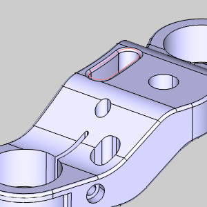
5. Extract Isocurve: Unveiling Surface Geometry
The ability to extract isocurves from surfaces automates a previously intricate process. Use the Extract Isocurve feature to pull wireframe geometry curves directly from surface data. Select the surface, set U and V direction values, and even use the mouse in the graphics area to determine the curve locations effortlessly.
| Trim Isocurves: Yes | Trim Isocurves: No | Created Geometry |
 |
 |
 |
.
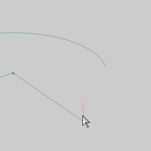
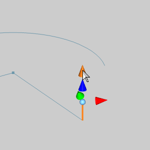
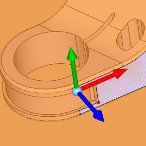
6. View to Active UCS: Streamlining Coordinate System Navigation
Navigating through different coordinate systems can be challenging. The Views to Active UCS option simplifies this process by aligning all views with the current coordinate system you’re working in. Click the ![]() icon in the status bar, and watch as views seamlessly adjust in relation to your active UCS.
icon in the status bar, and watch as views seamlessly adjust in relation to your active UCS.
| Create Custom UCS | Adjust Views Normal to the UCS |
 |
 |
.
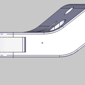
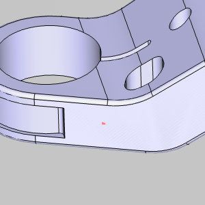
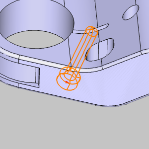
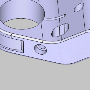
7. Advanced Holes: Revolutionizing Hole Creation
The Advanced Holes feature takes hole creation to new heights. Create complex 3D holes and assign threading information effortlessly. Select locations, input desired values, and watch as the hole, including drill tip and threading information, is generated!
| Select Point | Preview Updates with Parameters | Advanced Hole is Created |
 |
 |
 |
.
8. Add Property: Tagging Geometry with Thread Information
The Add Property function allows you to assign geometry thread information, essential for the Hole Recognition feature. Even if your existing part file lacks this information, the Add Property feature enables you to tag each entity efficiently, ensuring swift and accurate Hole Recognition.
.
9. Edit Property: Fine-Tuning Thread Information
After assigning properties with the Add Property function, the Edit Property function lets you fine-tune values effortlessly. Filter thread sizes, select the desired geometry, and update it with new thread information, providing flexibility and precision.
.
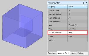
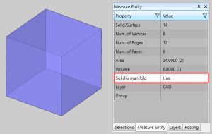
10. Solid is Manifold: Verifying Model Integrity
Building solids involves stitching surfaces or using boolean functions. The Solid is Manifold data point (true or false) is a crucial tool for verifying whether your edges are meeting properly. Open the Measure One function, select your model, and check the data point to ensure your model is ‘watertight’ without unseen problem surfaces. In the images below, you can see an examples of a properly, and improperly made cube to show this data point.
| Solid is Manifold: False | Solid is Manifold: True |
 |
 |
.
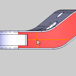
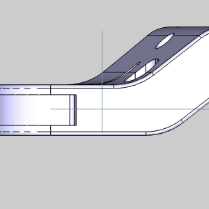
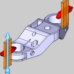
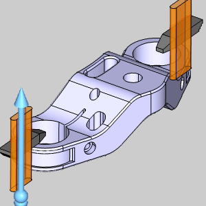
11. Extrude Body Interaction: Tailoring Solid Interactions
The Extrude Boss, Extrude Cut, and Advanced Holes functions now include the Scope section, allowing you to specify which existing solid bodies the feature should interact with. This level of control ensures that your design elements interact precisely with existing solids. In the images below you can see this used while adding unnecessary detail to our fixturing.
 |
| Selected Bodies | All Bodies |
 |
 |
| Fixtures Affected | All Bodies Affected |
 |
 |
.
In conclusion, the CAD features in BobCAD-CAM empower designers and engineers with enhanced precision, efficiency, and control. These features are designed to streamline your workflow and elevate your CAD design experience. Embrace the power of BobCAD-CAM and master the art of precision in your designs.


Leave a Reply